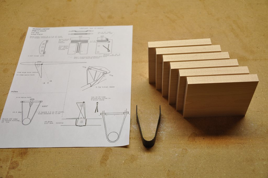
In order to make the V-Mount's Platform, I analyzed the plans and then various write-ups online. I experimented with a few ideas, and finally settled on what follows here. This is actually my 3rd variation on making a platform mold and I'm very satisfied with the results.
As with a lot of molds or forms I've made recently, I selected maple boards for making my mold. I specifically used 1/2 inch thick boards because various platform dimensions fall in roughly 1/2 inch increments.
I cut six boards of equal size - 4 x 3.5 inches.
Although not visible in the pictures, before I did anything else, I numbered the back of each board: 1 - 6 so that I'd always be able to keep the same alignment.
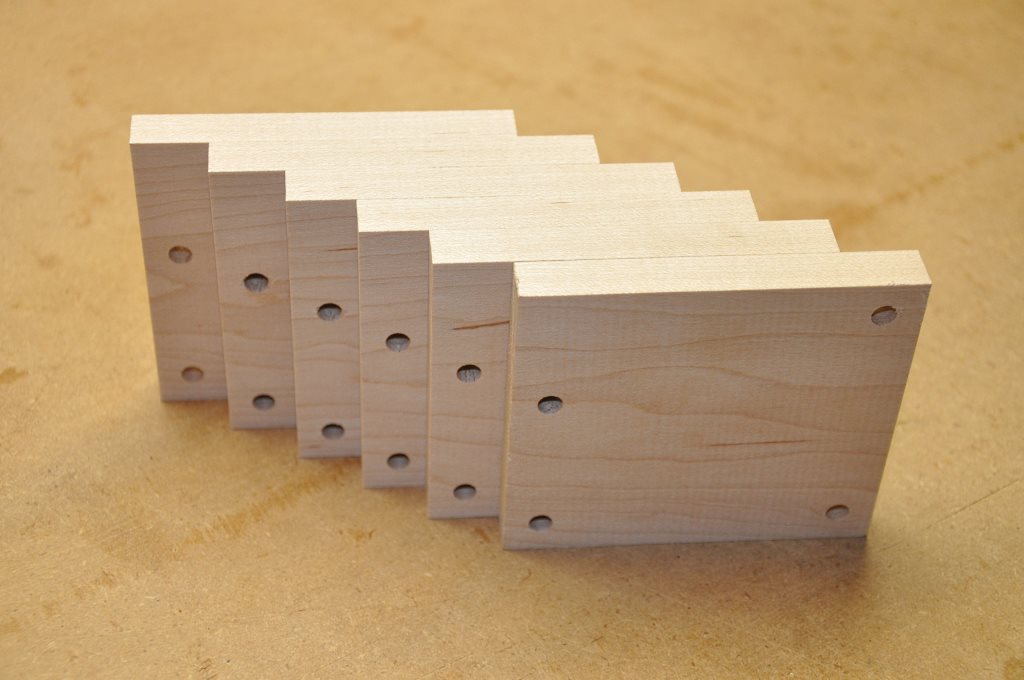
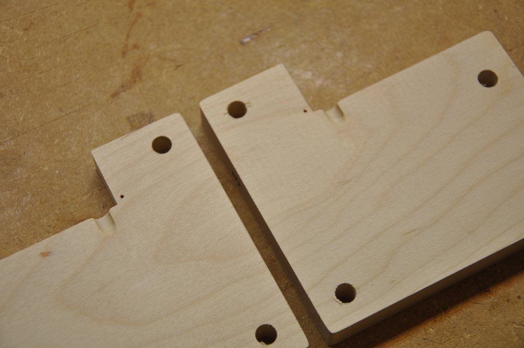
Next, I used my drill press to drill four 1/4 inch holes in the boards.
One of the holes is offset from the top, as this part will later be cut out to form the platform shelf.
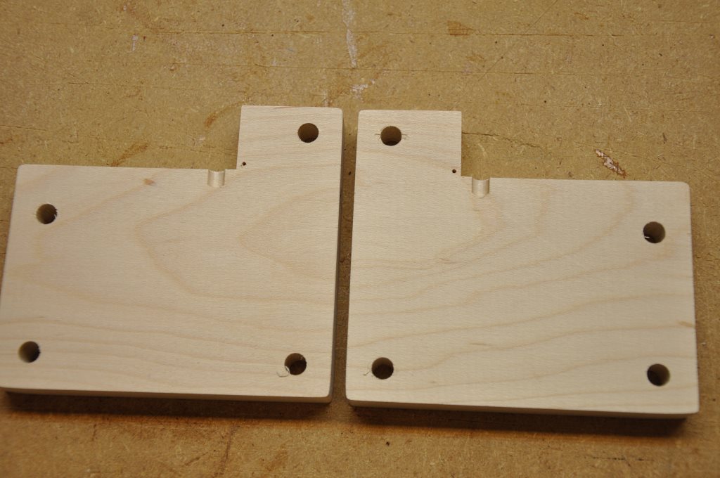
I inserted 4 bolts into boards 2, 3, 4 and 5 and then using my table saw, I cut the platform shelf.
Boards 1 & 6 do not get the shelf cutout.
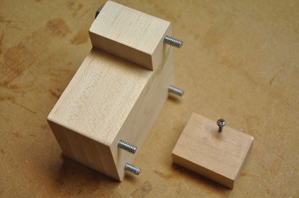
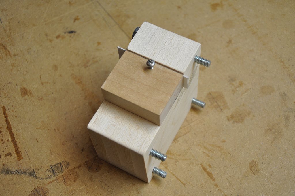
I also cut a scrap piece of maple to a width of slighly less than two inches to make the block that press the shelf from the top.
This block was drilled to receive the metal 6-32 bolt that will form the threads in the finished parts.
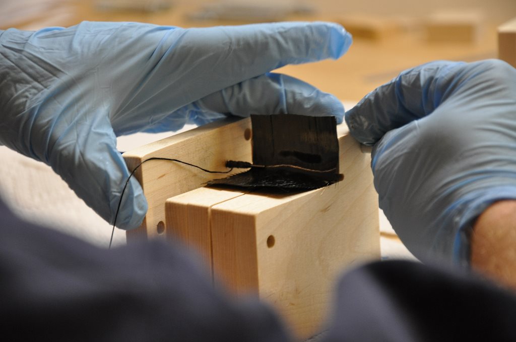
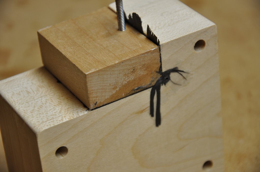
I blackened the end of the bolt and placed it in place over the other boards.
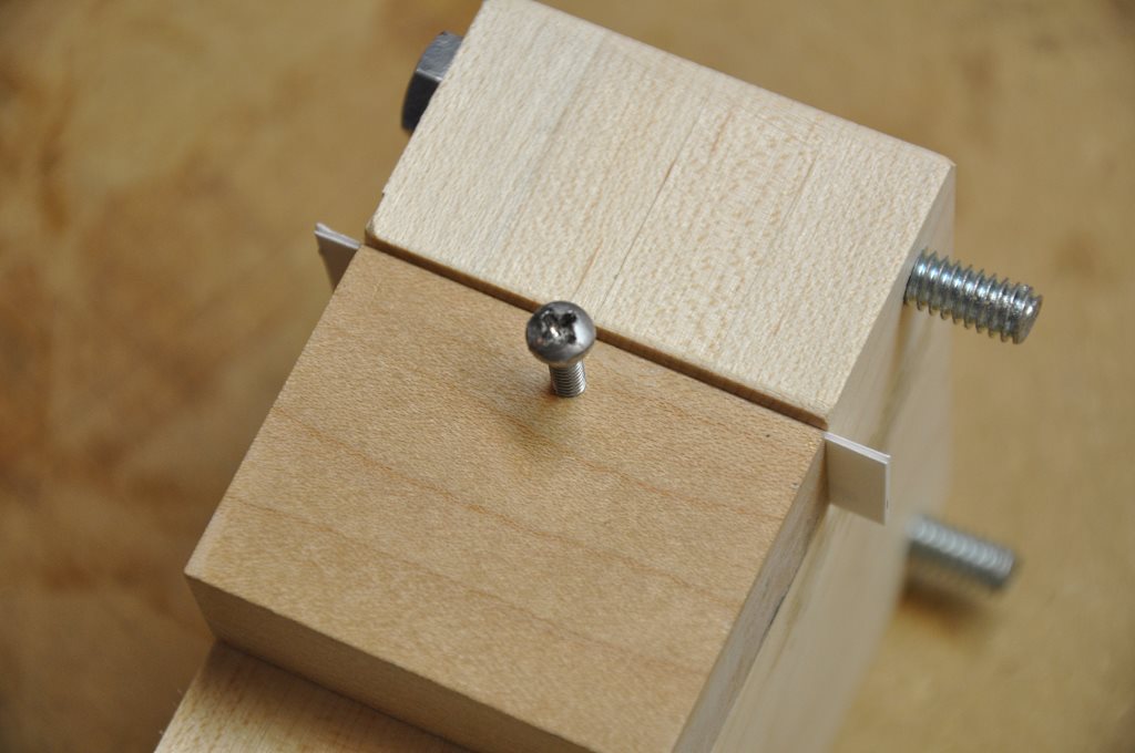
A small shim of card stock created the same offset as the carbon fiber fabric will create - thus ensuring that the screw location was accurate.
Using a screwdriver, I rotated the bolt back and forth a bit to transfer the black ink to the boards beneath it.
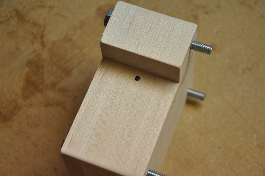
Here we see the location to drill the screw pocket.
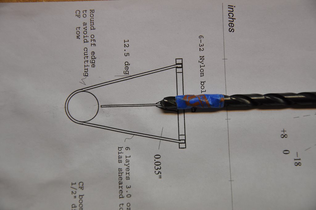
I taped off the end of a 7/32 inch drill bit to match the desired depth of the screw pocket.
Be sure that you don't make this pocket too deep - there is no need for that.
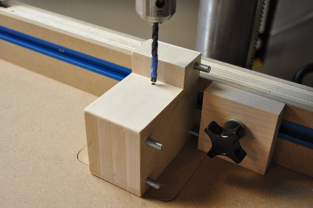
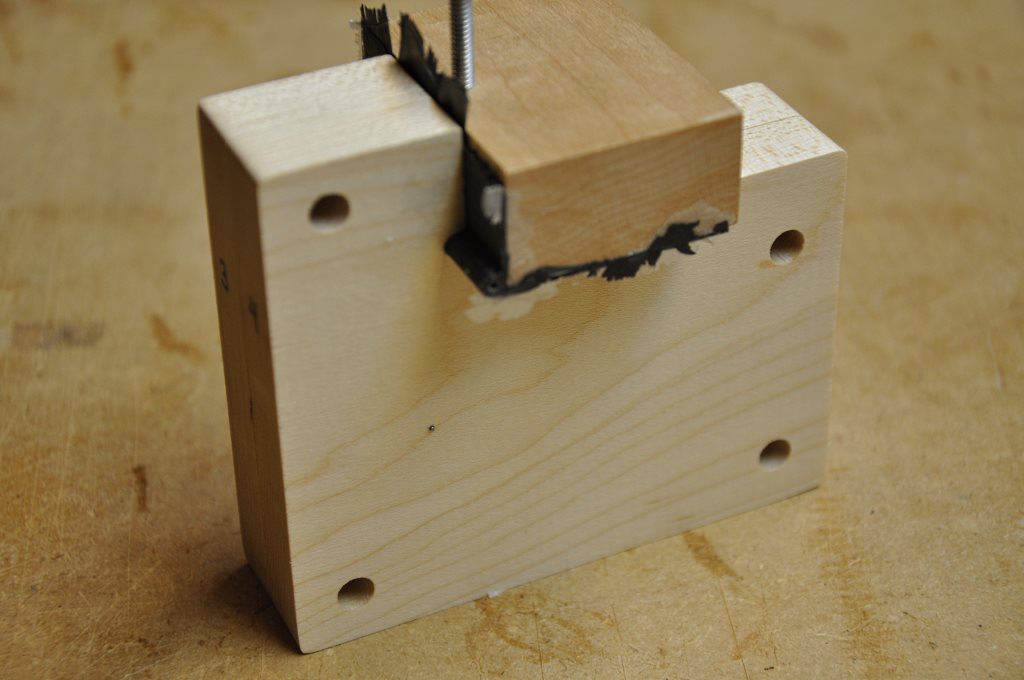
I then drilled the pocket hole to depth.
The hole is drilled.
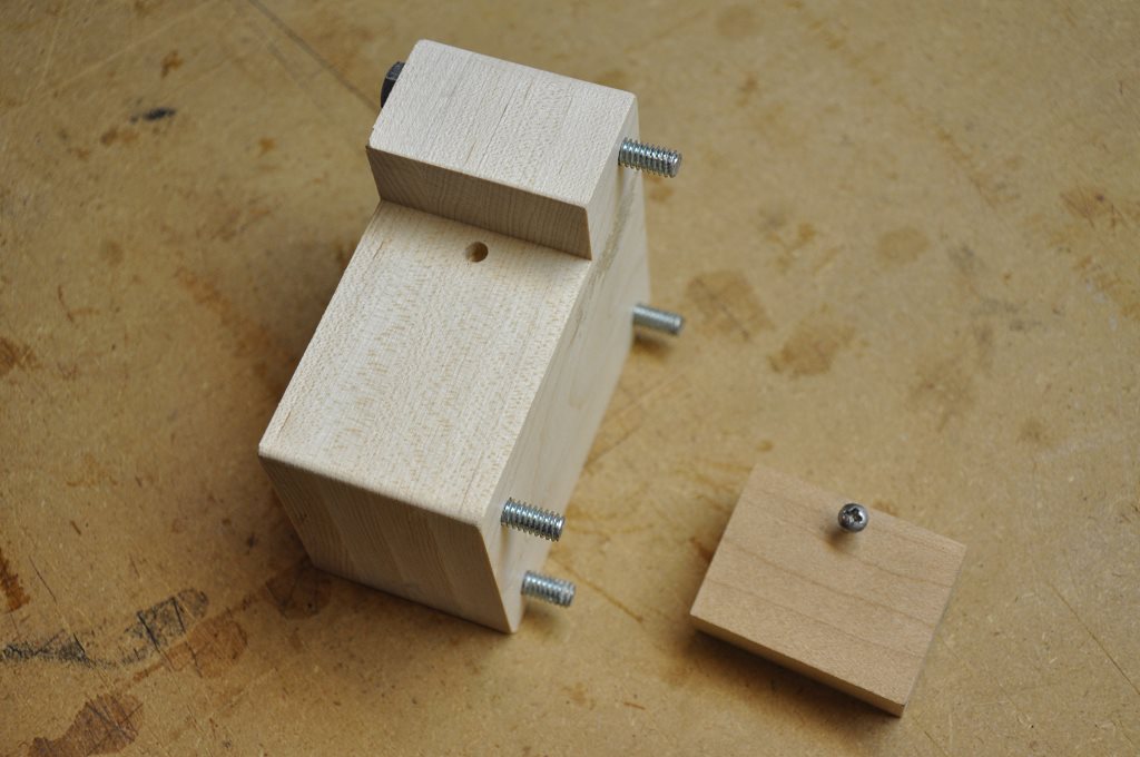
I screwed the bolt to it's molding depth and using the card stock shim, checked that the bolt sat properly in the screw pocket.
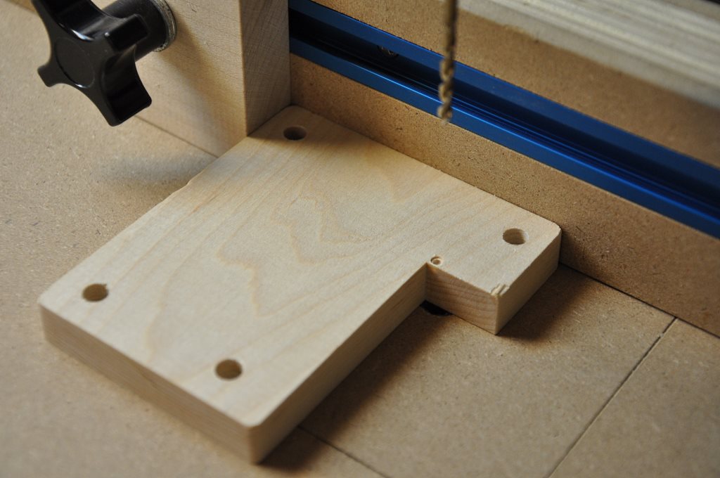
To create the recessed areas for the hinges, I drilled boards 2 & 5 with a 1/8 inch drill.
I made sure that the hole lined up perfectly with the bottom of the platform shelf, and was ever so slightly inside the platform fence.
Once these holes are drilled, cut away any wood between the hole and the fence side of the platform. Sand away any rough spots and ensure that your parts will be able to slide out from the hole after layup.
It is important now to keep the drill press fence and stop in the same location so that we preserve the hole location.
I removed the 1/8 inch drill bit and replaced it with a .047 inch drill bit. This is the exact diameter of the hinge wire that the final part will have.
You can see in this picture that the smaller drill fits in the center of the larger hole.
Now I drilled the .047 inch hole in boards 1, 3, 4 and 6.
These will be used to hold a .047 inch wire during the platform layup, thereby creating the holes for the hinge wire.
Also note in this picture that the screw cup recesses need to be flared to create a smoother transition.
Using a combination of round files and sandpaper, I carefully flared the screw cup so that there would be a smooth transition from cup to control horn.
Be careful not to overdo the sanding, as you want to keep the cup shallow...
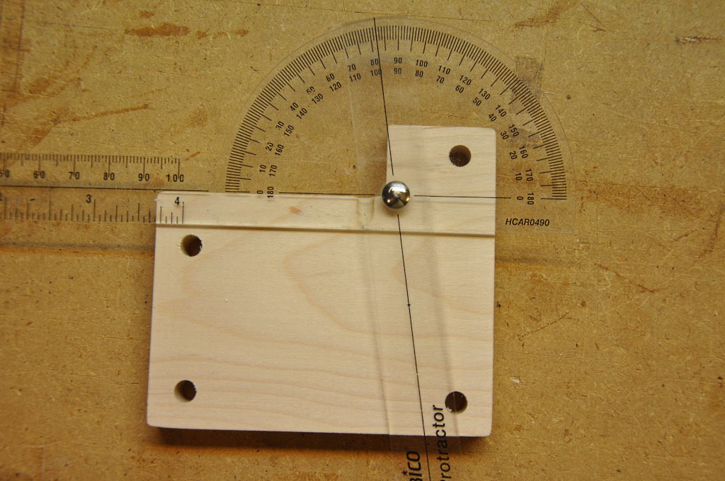
The plans show the stabilizer control horn's neutral position to be 8 degrees back from vertical.
I used my protractor to set that angle and then marked a point 32mm down from the platform.
That point is where we will drill the next hole.
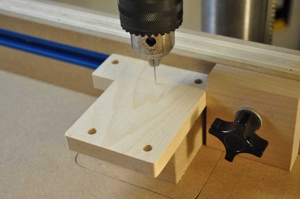
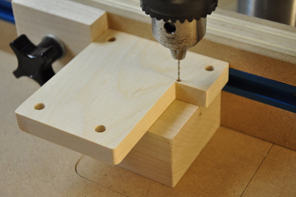
Using a .029 inch drill bit, I drilled holes in boards 3 & 4 at the control horn location.
Then using a larger drill bit, made a wider divot in each board at that hole to provide a slightly larger bearing surface for the pushrod.
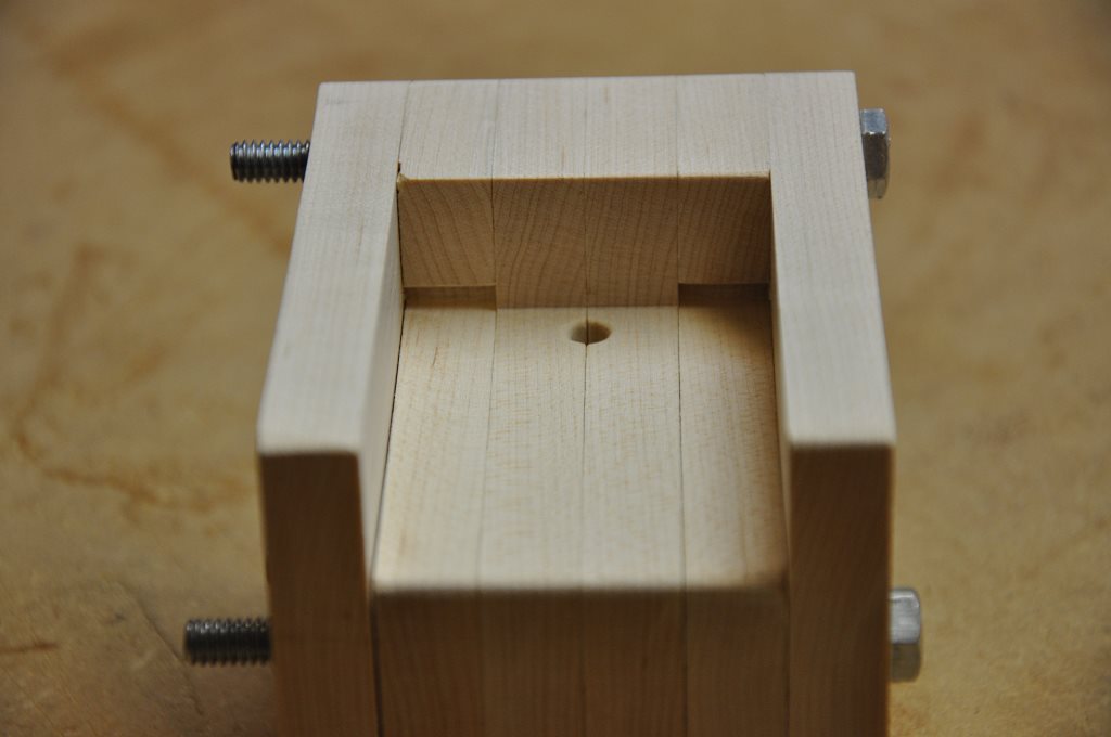
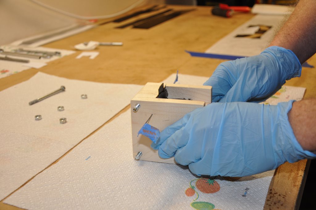
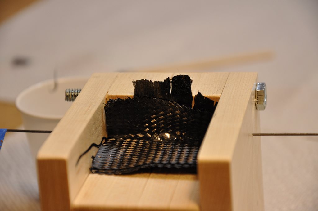
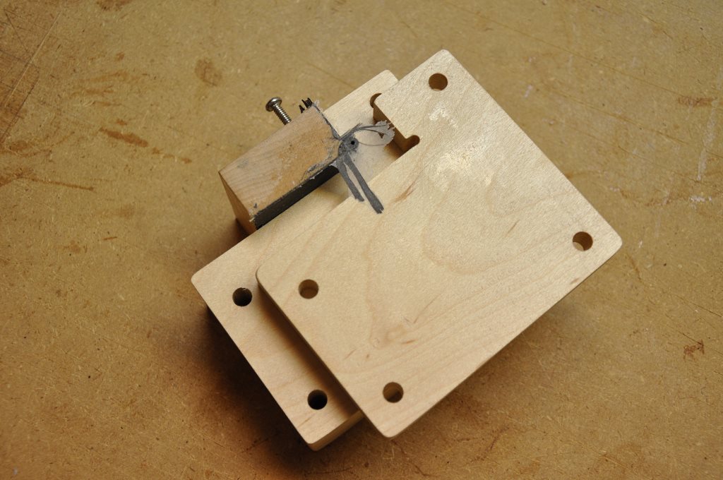
Using 3 1/2 inch long bolts, I fit the entire assembly together to ensure the proper fit of all the parts.
You can see here the way everything goes together and the recesses provided to create the hinges.
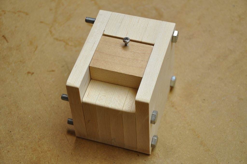
While everything is together, ensure that the small block fits and does not make contact with the side walls.
Once satisfied with everything, apply 3 to 4 coats of wax to all surfaces that might come in contact with epoxy
Dr. Drela recommends burnishing the metal screw with a wire brush to remove any small burrs from it, then wax the screw and any wires that you will use in the layup.
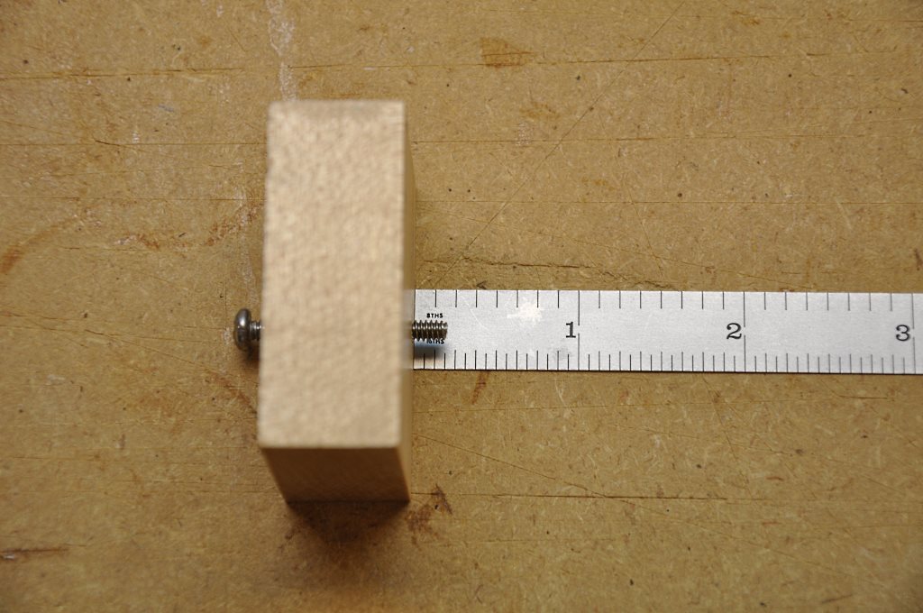
We are just about ready to start forming the platform. Set the depth of the 6-32 screw.
For my mold, I'm setting the depth of my screw to just slightly over 3/16 of an inch.
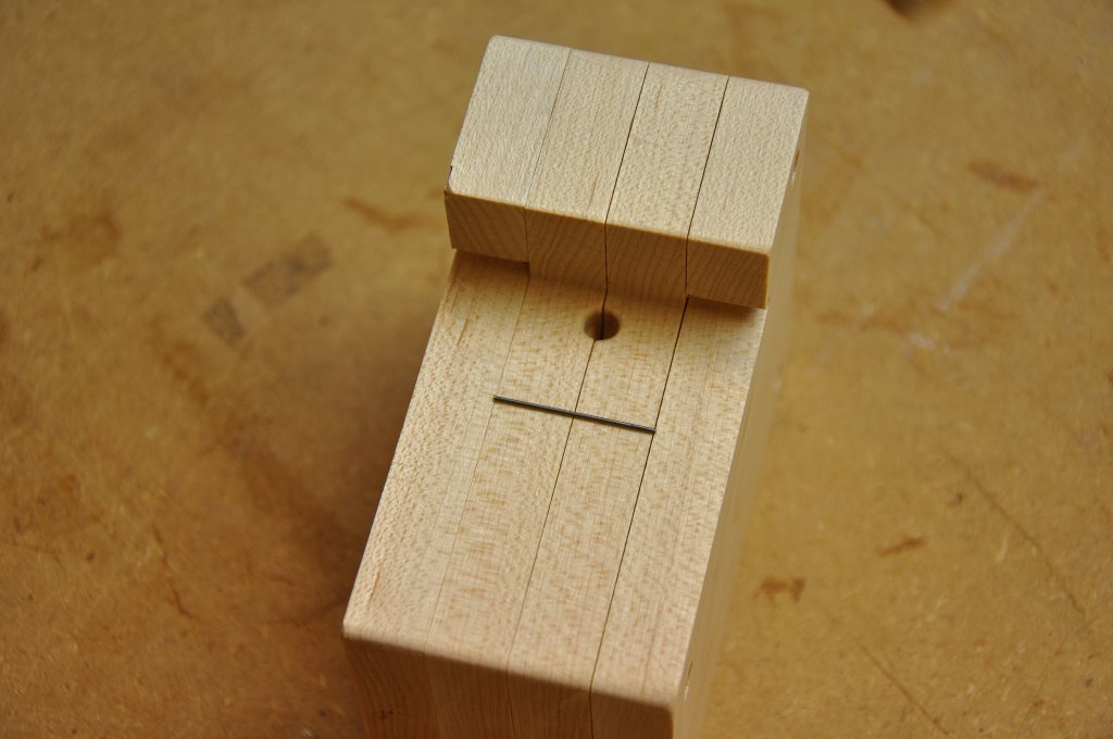
I cut a .029" diameter to 1/2 inch length. This wire will form the control horn hole.
This picture just shows how the wire will be held in place between the # 2 & 3 boards.
Disclaimer: The series of pictures that follow from here are of me molding the sixth platform I made. At this point I had figured out a process that worked well enough for me to reliably photograph.
Using 5.7 oz. carbon cloth, I cut a single piece of cloth to roughly 6" x 6" square on a 45 degree bias. I then gently pulled the cloth to a 20 degree bias as specified on the plans. I then spread laminating epoxy on the entire cloth, placed wax paper over it and forced the resin into the cloth with a hard rubber roller.
I then replaced the wax paper with paper towels and blotted up as much excess epoxy as I could.
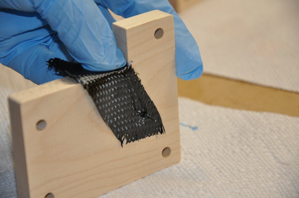
At this point, using some small paper templates I had made, I cut the shapes I needed from the carbon cloth. I then place the first piece over the mold.
I pushed the .029 inch wire through the fabric and then wrapped 2 1k carbon tow pieces 3 times each around the pin.
Note: In preparation for the layup, I had cut two 5 inch strips of carbon tow for the horn and two 20 inch strips of carbon tow for the hinges. These were pre-saturated with epoxy.
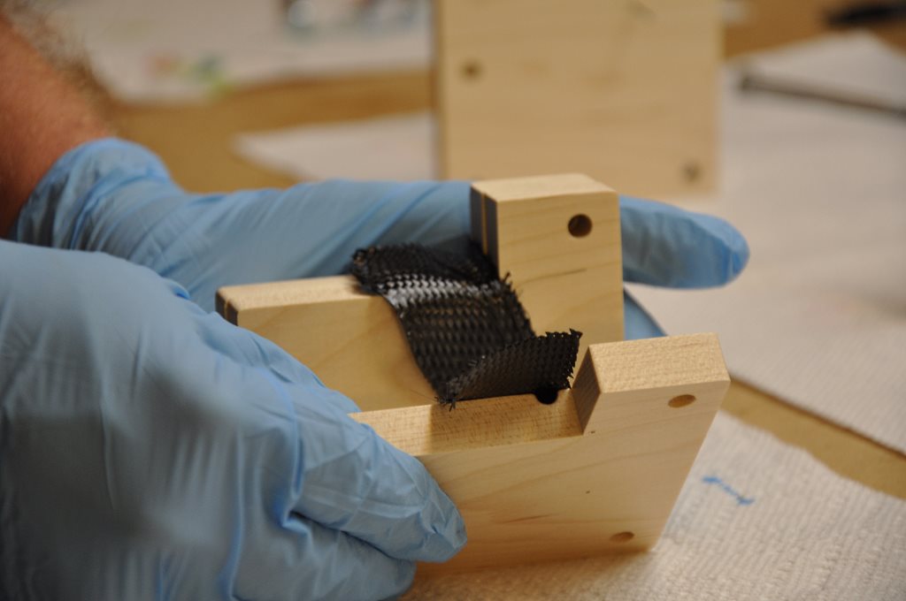
I placed the second carbon strip on the opposing board and carefully brought the boards together with the .029 inch pin fitting in the holes between them.
Now here I deviate from the plans a bit... (if you can do it without this so much the better.)
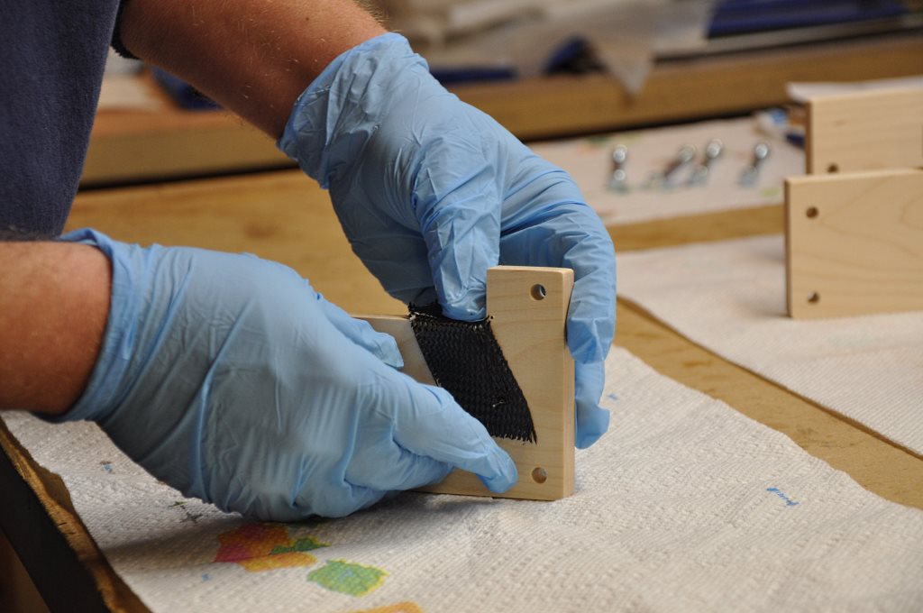
I mentioned that this series of pictures is the 6th part I made... one of the difficulties I encountered on the first few tries was getting the hinge "lugs" to reliably affix themselves to the platform fence.
My solution was to place 4 oz unicarbon on the platform with the fibers running the same direction as the split between boards. I cut two slits 1/2 inch in from each side, so the unicarbon would fold into the lug recess. - observe how, in the pictures below...
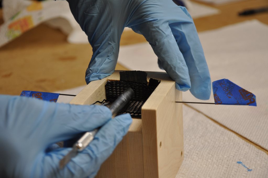
I pushed a .047 inch diameter wire about 3/4 inch through block #6.
Then I took one of my (pre-saturated) 20 inch long 1k carbon tow pieces and started winding it around the wire until it covered 1/2 inch of the wire with about 1/8 of an inch diameter.
For what it's worth, I had wound a dry length of tow around the wire during planning to determine what length was needed to fit the hinge pocket correctly - your length will vary based on the size of your hole...
I then carefully pushed the tow-wrapped wire and the unicarbon into the hinge lug recess - ensuring that the small bit of exposed wire locked into the hole in the #4 board.
I took the #1 board, inserted another .047 inch wire and repeated the tow-winding process on that pin.
Then I pushed the pin into it's slot in the #2 board.
Bringing the parts together...
Here is a shot of the 5.7 oz. carbon cloth that I'm getting my pieces from. I settled on this method for speed mostly as it is easier to spread and blot one large piece of carbon instead of 4 small pieces.
Now, using another paper template I had previously made, I cut 2 rectangular pieces of cloth that will be used for the platform and fence.
I placed the two carbon rectangles into the platform shelf area and gently pressed them into the corner.
Note the orientation of the fibers on the plan. The fibers need to be aligned mostly across the width of the platform...
Next, I slid the bolts into the 4 holes in preparation for clamping.
At the same time that I had mixed the epoxy for the carbon fabric and carbon tow, I poured a tiny bit of epoxy into a cup with chopped strands of carbon fiber.
This I mixed together and pushed into the screw cup recess in the mold. This will flow around the screw and form the threads for the nylon stab mounting bolt.
Note: the plans call for using cotton flox for this, but I discovered that the white flox shows through the carbon in an unsightly way, so rather than adding graphite powder to blacken the cotton, I just used carbon strands instead...
Here you can see the carbon flox mixture in the screw cup recess.
Now I brought the screw block form into position with the rest of the mold.
Press the block firmly into place.
You want a nice square bend between platform and fence and the screw needs to achieve its proper depth.
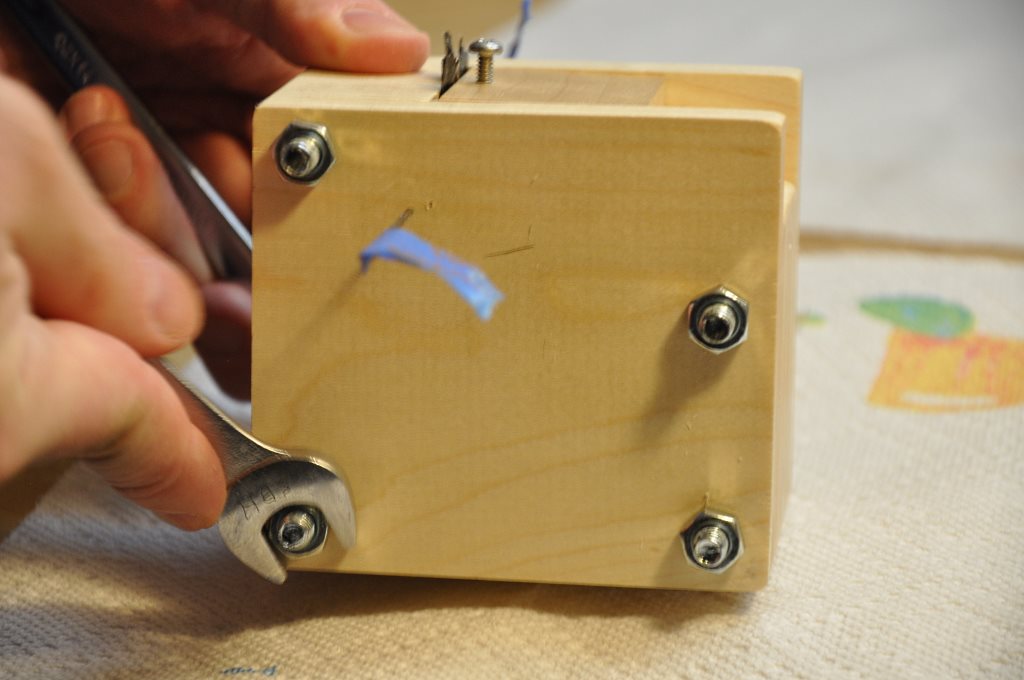
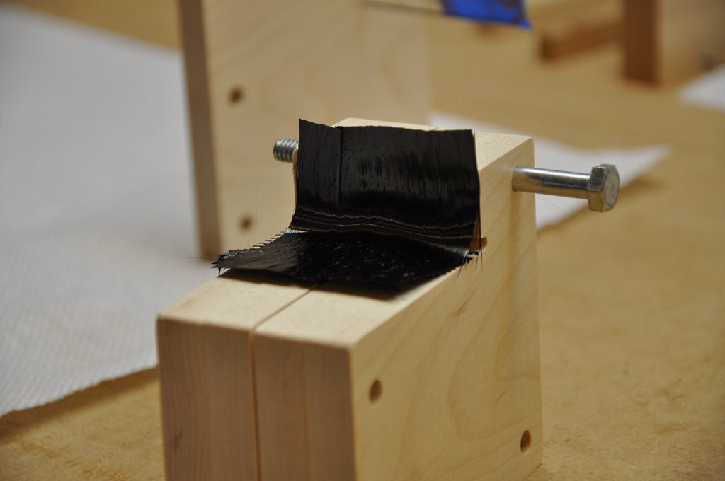
Once everything was in place, I tightened the nuts onto the bolts.
I then clamped everything in place.
The nice thing about maple is that it's hard enough to take some serious force without deforming.
I'm using these clamps to force the screw block into it's place. I want to make sure that the platform and fence receive maximum clamping - this also ensures that all the material in the hinge lugs is forced to fill the hinge lug cavity - no gaps at all.
One other thing to note: remember that extra carbon cloth I had left over from cutting my pieces for the platform? Don't throw it away, instead, layer 2 or 3 pieces of it together to make the control horn for the rudder.
The flat board under clamps has that extra carbon...
I put my "hot box" over the clamped parts and let them cure overnight.
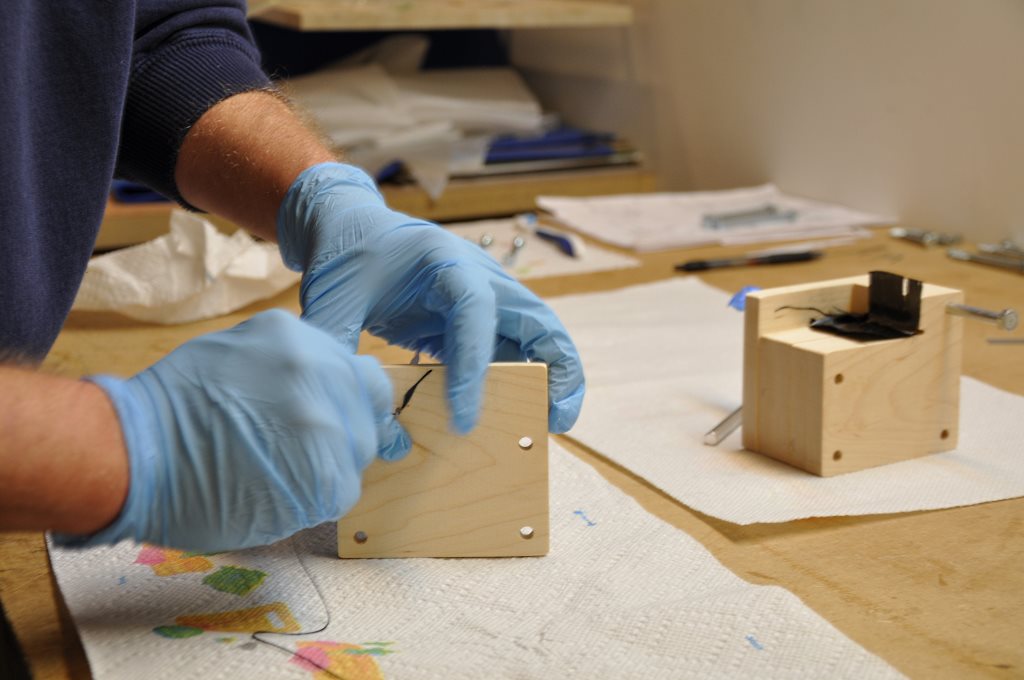
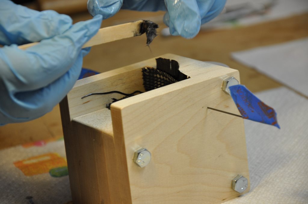
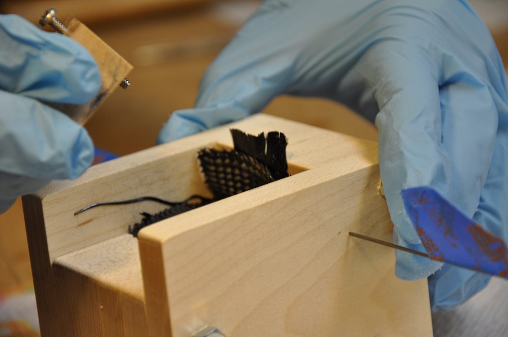
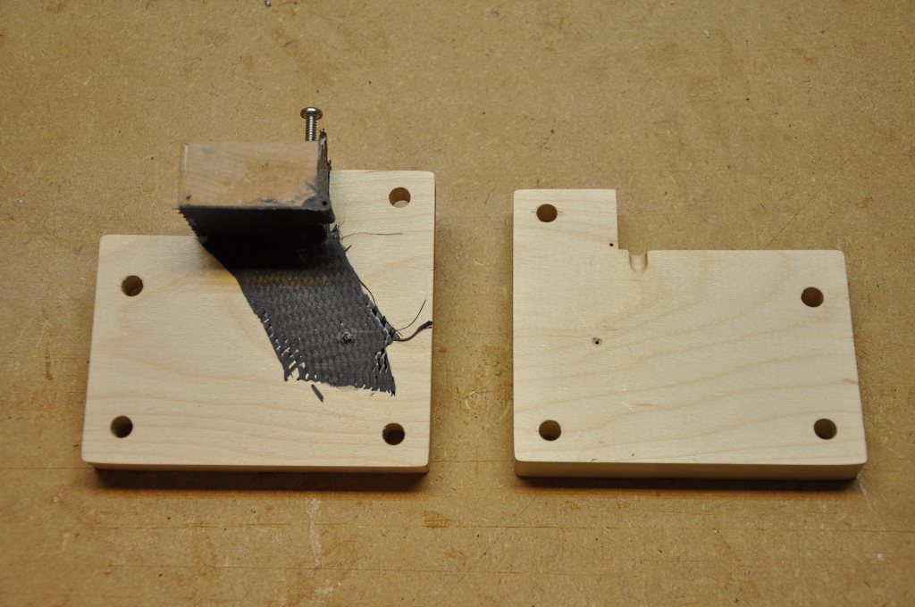
In the morning I started pulling everything from the mold.
First I backed off the screw until it was completely removed from the carbon platform.
Then I pulled boards 1 and 6 away from the others. A little twist of the wire with a pair of plier might be needed to get it to come free of the part.
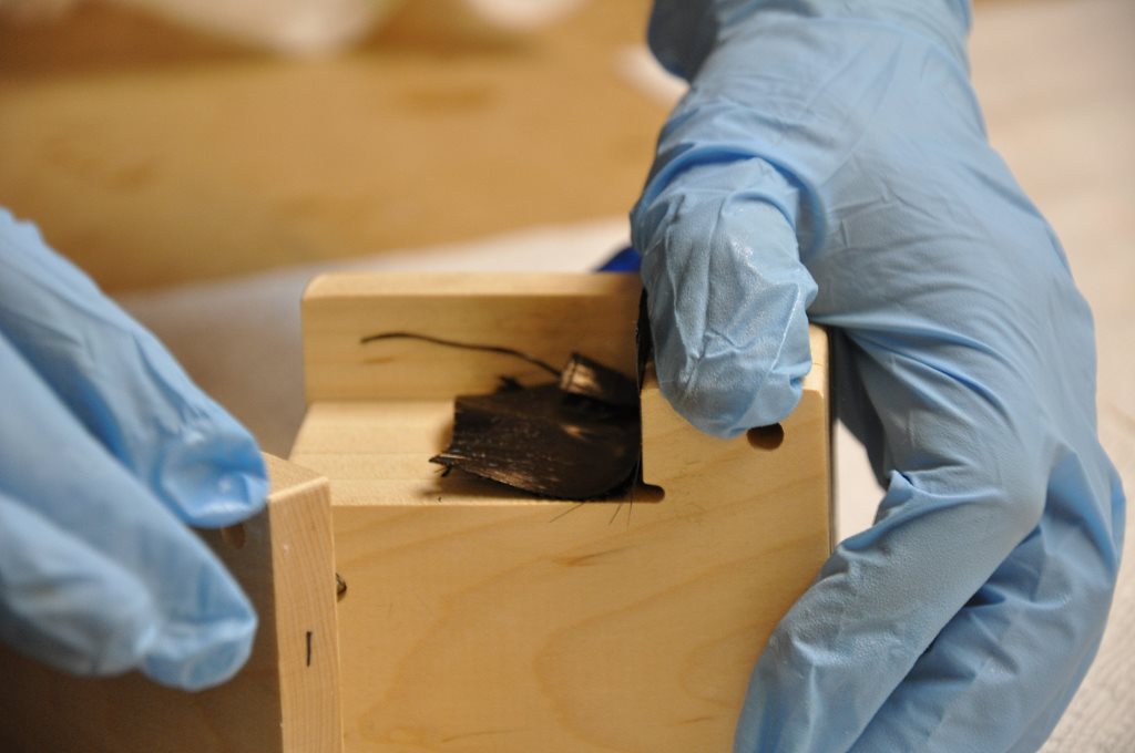
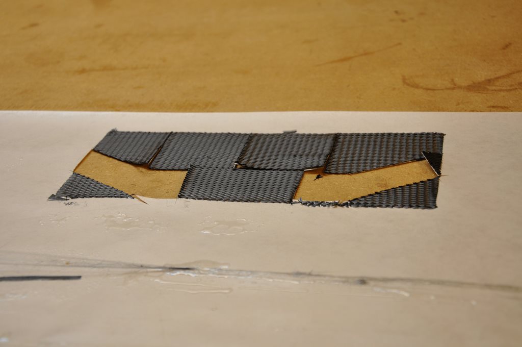
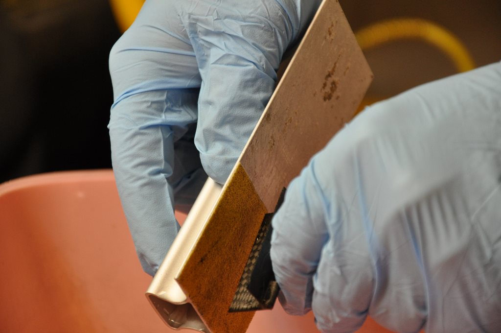
Here is a close-up of the hinge lug area. You can see the nice hinge pin hole that we have formed.
Don't worry about the ugliness of the part as it comes from the mold - all of the junk will be shaped away.
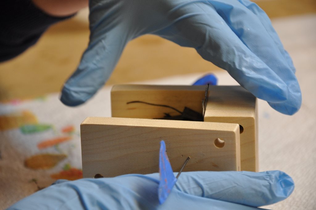
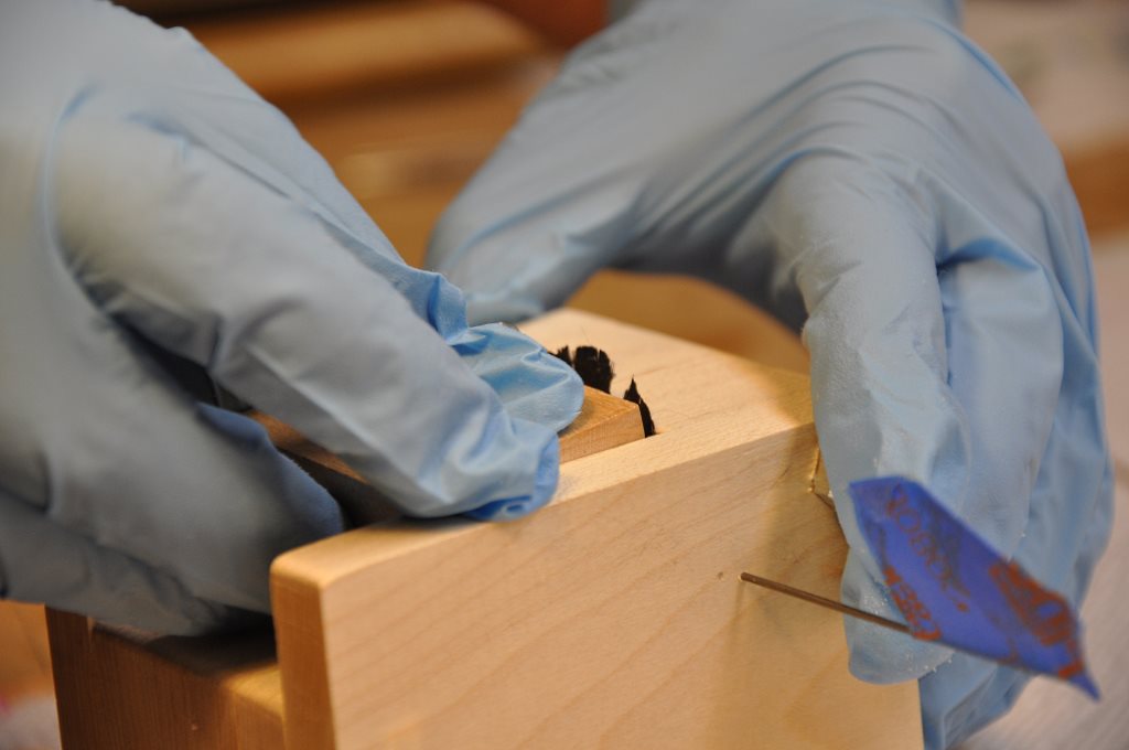
Gently remove blocks 2 & 5 from the part.
Take exceeding care with these blocks. The hinge lugs are in there and we don't want to put forces on them that might cause them to crack.
The nice thing with mine, was that I had waxed them so well that they literally fell off the hinge lugs. Yay!
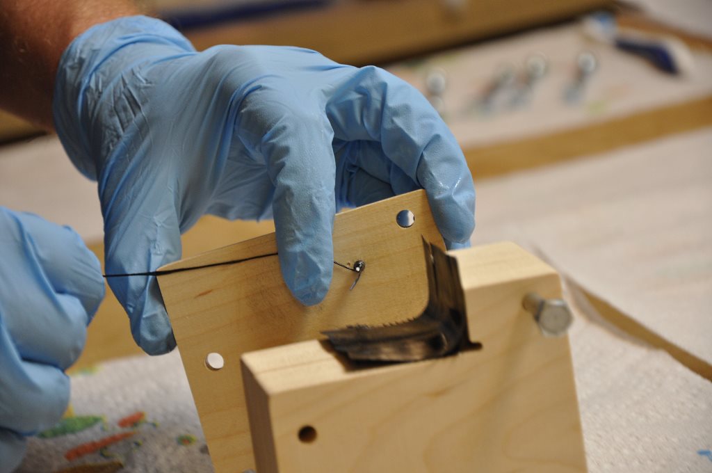
Now we need to get the .029 inch wire out from boards # 3 & 4 before we can separate the rest of the pieces.
You can see the wire just peeking out of its hole.
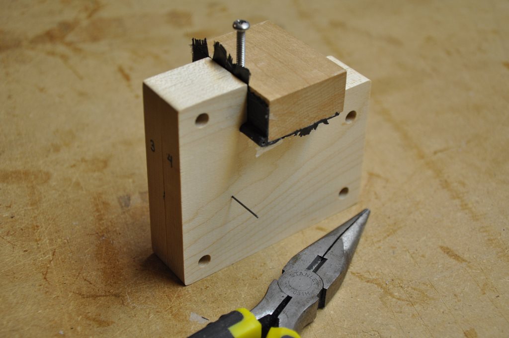
I pushed on the pin from one side and the used my pliers to pull it the rest of the way out.
Then I was able to separate the final two boards and remove the screw block.
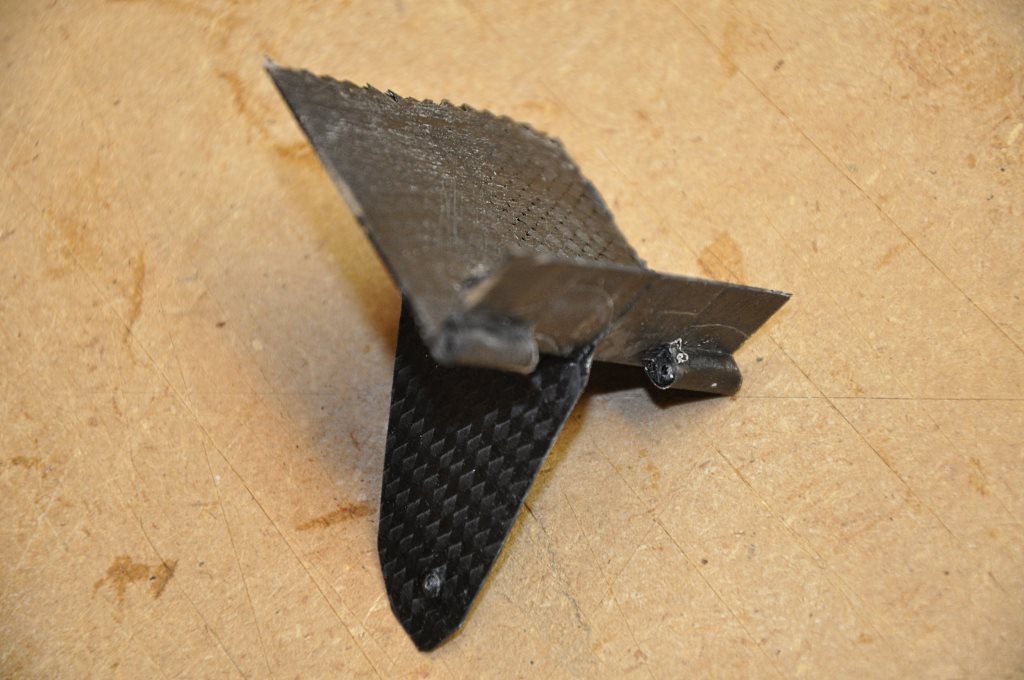
Note: you can see in this picture, both the divot for the pushrod hole in the mold and the resulting dimple on the control horn in the final part.
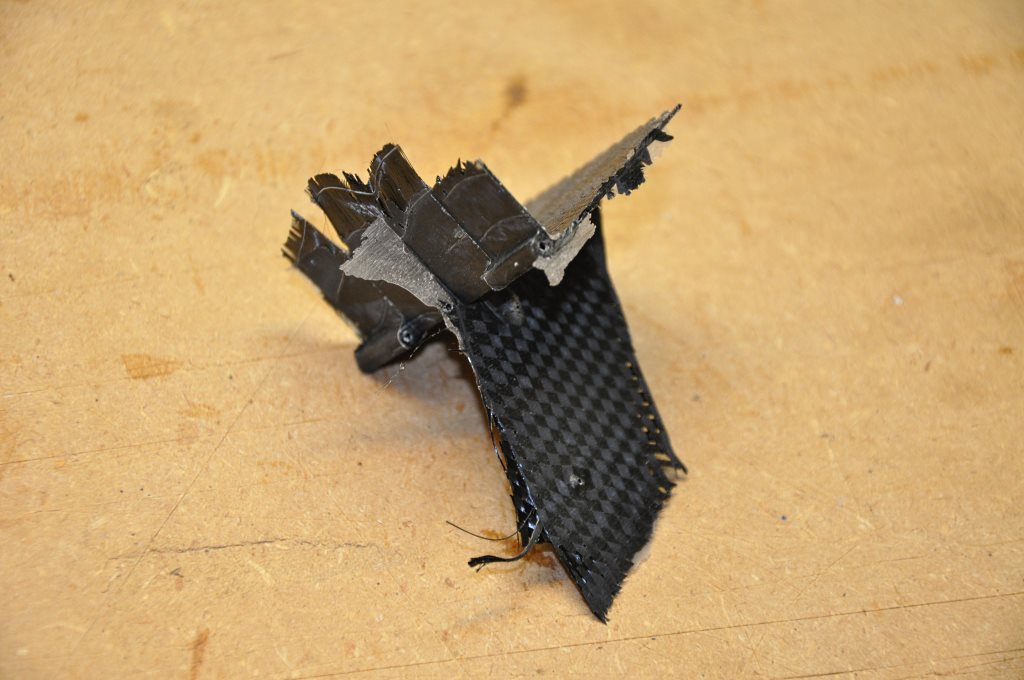
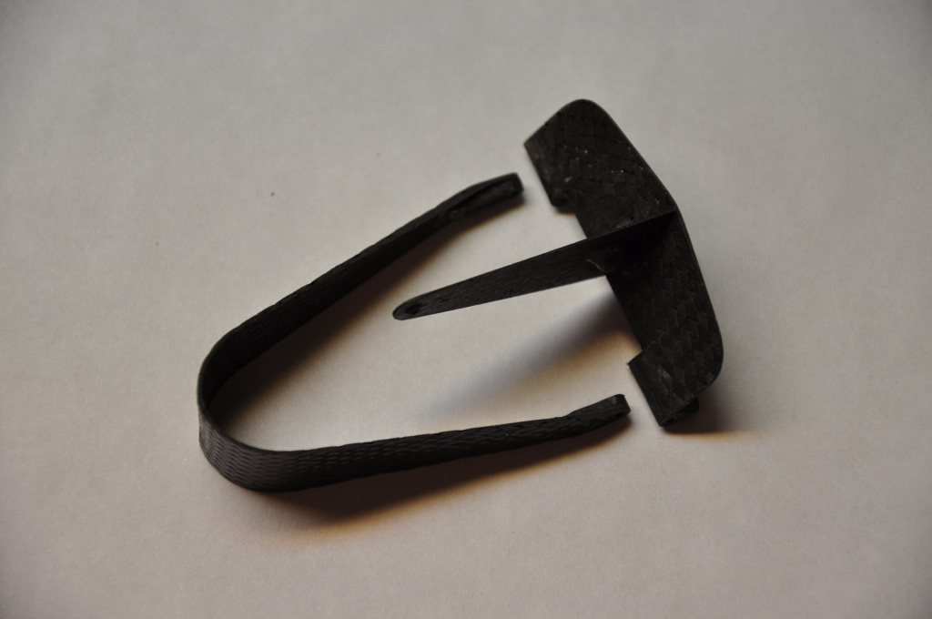
Raw and ugly, as it comes from the mold.
Not to worry, we will shape it into a work of art! :-)
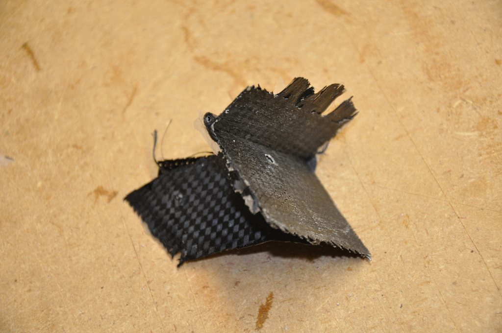
Just a different view of the part as it came from the mold...
I have a lot of excess material on the raw part that I trimmed off with a pair of scissors.
Once I trimmed closer to the final shape, I was ready to do the detail shaping with sand paper via wet sanding.
I put on gloves and a face mask and goggles to protect me from any stray carbon dust - although the wet sanding pretty much keeps everything under control, I'm not taking any chances...
I got a small tub full of water and wet both the part and my sanding block and went to work bringing the final shape to the platform.
Once the platform (and the v-strut) have been shaped it is time to bring them together.
Since I am not doing a big production run, I'm simply going to custom fit each platform and strut to each other.
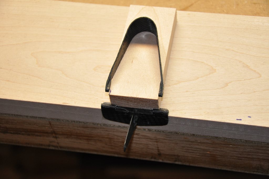
I cut a block of Maple to the exact width of the inside of the v-strut.
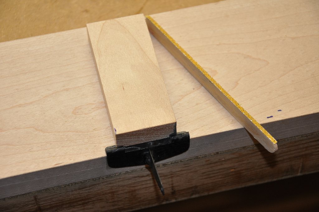
Next, I hunted around my shop for a metal file the exact width of each of the v-strut legs, and not finding anything, I just glued some sandpaper to a hard stick that happened to be the correct width.
Note, that I left the side of the stick clean - this will make a nice bearing surface against the Maple block to guide the sanding process.
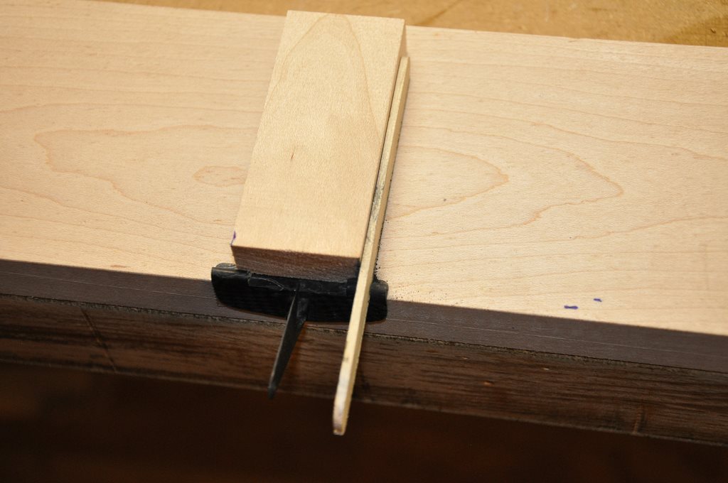
Carefully sand the notches in the platform to receive the v-strut.
Unfortunatelly, wet sanding here makes too much of a mess, so cover up well and vacuum often...
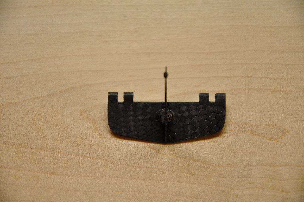
Here is the platform almost ready.
Some continued trial fitting is necessary to ensure the proper movement of the pieces.
The plans call for +8 to -18 degrees of movement. You want to ensure that you have at least that, and maybe a bit extra for good measure...
Finally take your .045" hinge pins and insert them into the mount. A drop of CA can be used on the ends of the platform to secure the pins in place. On mine, the fit was so snug, as of yet I have seen no need for adding CA - but I'm keeping an eye on it...
If any of the pins protrude, file the ends flush.
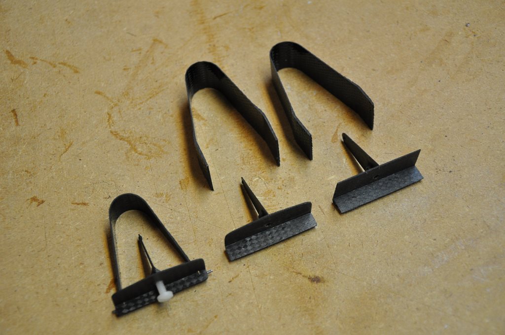
Several V-Mounts in various states of final shaping and assembly...